Installing FreeBSD 14 on IONOS VPS hosting

About IONOS VPS

IONOS provides cheap Linux VPS hosting with full root access and unlimited traffic. It also provides a KVM console to administer out-of-band if needed. The only problem is that it does not support FreeBSD; the only available options are Linux flavors. However, I found that installing and using FreeBSD 14 using the mfsBSD project is possible. Internally, IONOS uses the Microsoft Hyper-V platform, which FreeBSD supports.

Initial setup

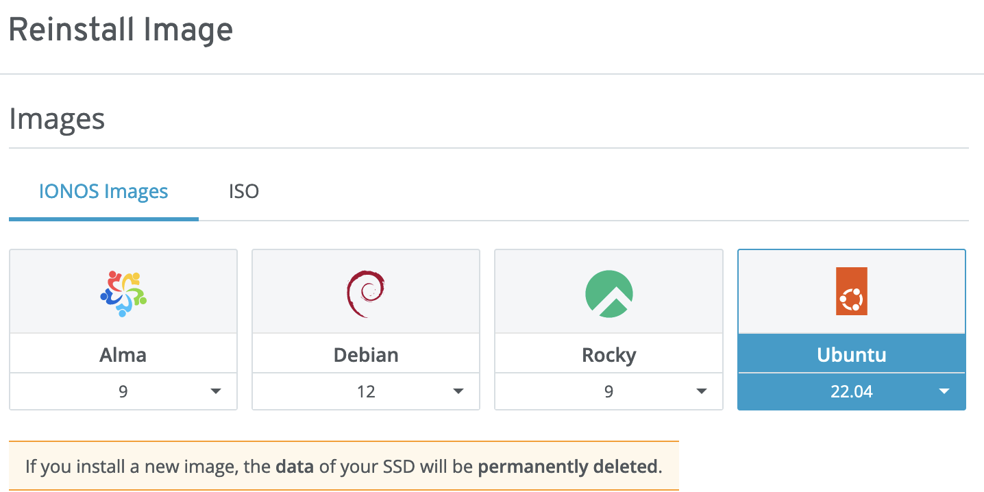
To install FreeBSD, we must choose any Linux option from the “Images” tab. I have chosen Ubuntu 22.04; however, any selection would likely work the same. Once installation is completed, go to the “Servers” tab, select your VPS, and use the “DVD Drive” menu, which allows you to boot the VPS from the recovery CD. Select “Debian 12” ISO and click "Load DVD.” Once done – open KVM using the “Actions -> Open Remote Console” menu. Go to the shell using the “Advanced Options -> Recovery” menu. Choose “Do not use a root file system” in the filesystem dialog and execute a shell. It will be used to install mfsBSD.

mfsBSD installation

First, we will install mfsBSD which would allow us to boot and install FreeBSD 14 using KVM.

From the Debian console download and write to the VPS disk mfsBSD 14 image:

wget https://mfsbsd.vx.sk/files/images/14/amd64/mfsbsd-14.0-RELEASE-amd64.img
dd if=mfsbsd-14.0-RELEASE-amd64.img of=/dev/vda

Go to the IONOS cloud panel and eject “Debian” ISO. Reopen the Remote Console; you should see FreeBSD booting. There will be a significant (~1 minute) delay after USB init, but the system should start normally after some time.

FreeBSD installation

Once mfsBSD starts, you can normally ssh the server (if IP is already assigned) using root/mfsroot credentials. Now the partition table is corrupt, and we need to fix it using the gpart recover vtbd0 command.

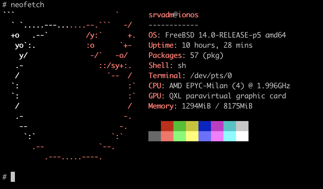
Run the bsdinstall command and use the vtbd0 disk to set up the system. I recommend removing original freebsd-ufs partition to avoid any traces of the mfsBSD setup. Follow the installation process normally, and use DHCP as a network option. Once installation is done, reboot the system, and FreeBSD 14 should start normally.

Reducing boot time

This is an optional step that impacts only boot time. FreeBSD spends significant time in USB stack initialization, which adds about 1 minute to the boot process. Also, it loads many “emulated” devices, such as floppy or serial controllers. According to kern.boottrace.log, the total measured time is 113579 msecs, about 2 minutes. To reduce this time, it is possible to use minimal kernel configuration.

First, we will need to install the src component and update the system:

fetch http://ftp.freebsd.org/pub/FreeBSD/releases/amd64/amd64/14.0-RELEASE/src.txz
tar -C / -xvf src.txz
freebsd-update fetch && freebsd-update install

Now let’s install MINIMAL kernel configuration:

cd /usr/src/
make buildkernel -j `sysctl -n hw.ncpu` KERNCONF=MINIMAL && make installkernel KERNCONF=MINIMAL

The ufs module must also be added to the /boot/loader.conf; otherwise, the system will not be able to boot. This is my /boot/loader.conf content:

kern.boottrace.enabled=1
autoboot_delay=1
ufs_load="YES"

Once done – reboot the system. Load time should be reduced from ~2 minutes to 5 seconds!

Enabling IPv6 and fixing “Bogus Host Name” warning

IONOS uses DHCPv6+rtsol to assign IP address and routing configuration for the IPv6.

First IPv6 address needs to be added to the IONOS control panel. Once it is done – the DHCPv6 client needs to be installed: pkg install dual-dhclient-daemon. This is my network configuration in /etc/rc.conf file to support both IPv4 and IPv6 with dynamic addresses:

ifconfig_vtnet0="DHCP"
dhclient_program="/usr/local/sbin/dual-dhclient"
ipv6_activate_all_interfaces="YES"
ipv6_defaultrouter="fe80::1%vtnet0"

Another small issue i found was dhclient[48327]: Bogus Host Name option 12: My_VPS (My_VPS) message every few minutes in the log. This is related to non-RFC compliant hostname returned by the ionos DHCP server. To ignore it – add /etc/dhclient.conf with a following content:

interface "vtnet0" {
  ignore host-name;
}

and restart DHCP client using service dhclient restart vtnet0 command.

This is it. I will keep this post updated in case of any other problems or optmisations found.

Tagged

Updating FreeBSD on armv6 board (RPI-B)

One of my old home automation boards running ebusd is still using Raspberry PI 1 B SoC. FreeBSD is still perfectly supporting this hardware, however, due to being a Tier-2 platform, binary updates freebsd-update are not supported. Of course, one can download the new image, but this will mean re-installing and reconfiguring all the software, which is time-consuming and painful. Also, the traditional “build from source” way will probably take forever on this tiny board and also could potentially destroy the SD card. So obvious alternative was cross-compilation.

To build kernel and world I used the amd64 host.

  1. Checkout FreeBSD source for the specific release you want to upgrade to (e.g. FreeBSD 13.2 in my case)

    git clone -b releng/13.2 https://github.com/freebsd/freebsd-src
  2. Compile FreeBSD kernel and world. Keep in mind, that RPI should use a non-generic kernel (RPI-B), otherwise the kernel will not boot.

    cd freebsd-src
    make -j 8 TARGET=arm TARGET_ARCH=armv6 KERNCONF=RPI-B buildkernel
    make -j 8 TARGET=arm TARGET_ARCH=armv6 buildworld

  3. It’s time to generate release packages:

    sudo make -C release/ TARGET=arm KERNCONF=RPI-B TARGET_ARCH=armv6 kernel.txz
    sudo make -C release/ TARGET=arm TARGET_ARCH=armv6 base.txz
    sudo make -C release/ TARGET=arm TARGET_ARCH=armv6 src.txz

  4. Copy txz files from /usr/obj/usr/home/srvadm/buildbsd/freebsd-src/arm.armv6/release/ to the target host, e.g. using scp, and unpack them. It’s recommended to copy /boot/kernel to the /boot/kernel.old before. If you plan to use GDB extract also “-dbg” archives.

    tar xf kernel.txz --clear-nochange-fflags --unlink -C /
    tar xf base.txz --clear-nochange-fflags --unlink --exclude etc/ --exclude var/ -C /
    tar xf src.txz --clear-nochange-fflags --unlink -C /
    etcupdate
  5. Now it’s time to reboot. Once booted – upgrade all ports using pkg upgrade command and delete old files using cd /usr/src && make delete-old && make delete-old-libs command.

That should be it, uname -a returns FreeBSD rpi 13.2-RELEASE-p1 FreeBSD 13.2-RELEASE-p1 releng/13.2-n254621-08b87f63a046 RPI-B arm output.

Tagged , , ,

Using EP-54V-150W as a home UPS

In my living area power outages are not common, however, they may happens in the middle of the meeting and also sometime there are series of on/off events, what is quit disruptive for the home network equipment. After all i decided to get UPS for my small rack. Most of my network devices (with exception of router) are PoE powered and PoE switch has 54V DC input already. So to avoid double AC->DC->AC conversation i was looking for the DC UPS with a 54V output. After all i decided to try Ubiquiti EP-54V-150W – it is DC UPS with WEB UI, SNMP and external battery support. Router was connected usign DC-DC converter.

Device description

The device is modular and comes from the shop with an AC module only. To use it as UPS another (DC) module needs to be added. The device could be connected to external batteries (2,3 or 4 serially connected) and 54V consumers (front door socket). The device could be managed using the web interface, SNMP, or ssh (username ubnt using 0 uid, so it is effectively root) using an ethernet port. Device firmware is using Linux kernel 2.6.32 and MIPS CPU with busybox and proprietary tools. It is possible to use internal or external chargers for the batteries.

Monitoring

Basic monitoring is provided in the web UI, however, it lacks some important fields, like charge/discharge current and historical data.

Also, it is not possible to set alerts in it. So after all I decided to integrate it with Grafana + InfluxDB which I already using for my smart home setup.

To get the data I started with SNMP option. MIB files are provided on the firmware download page and the snmpwalk tool shows that most of the fields I am looking for are exported. I am using the Telegraf tool to import SNMP data to InfluxDB. However, it was found that the battery charge/discharge current is not exported, so I had to find another way to export it.

After playing with the ssh console and reading forums I found a non-documented psuctl tool that exports a lot of data missing in the WEB/SNMP:

EP.v1.11.0# psuctl
Ubiquiti PSU control tool v0.1
Copyright 2006-2022, Ubiquiti Networks, Inc. 

This program is proprietary software; you can not redistribute it and/or modify
it without signed agreement with Ubiquiti Networks, Inc.

Usage: psuctl [options] 
	-p 	 disable/enable PSU
	-s 	 disable/enable PSU standby mode
	-c 	 disable/enable PSU charge mode
	-b 	 change battery unit count for DC/DC PSU w/ G0922
	-i		 display PSU information
	-o		 display output information
	-a		 display active alerts
	-A		 display alerts history

EP.v1.11.0# psuctl -i
PSU#0 [AC]:
  enabled: yes
  connected: yes
  standby: disabled
  charge: disabled
PSU#1 [DC]:
  enabled: yes
  connected: yes
  standby: enabled
  charge: enabled
  batteries [2]: 27.018V
    operational: yes
    charging: no
    temperature: 37C
    current: -0.010A

This tool also exports battery current, so I wrote a small script to grab it from the SSH and export to the format that telegraf expects:

#!/bin/sh

ssh -i /usr/local/etc/telegraf.d/id_rsa \
    -o StrictHostKeyChecking=no -o UserKnownHostsFile=/dev/null -o LogLevel=error \
    ubnt@psu.local psuctl -i 1 | \
    awk '/current:/ {gsub("A","",$2); print "psu_ssh,host=psu batt_current="$2}'

My Telegraf configuration is available on the github.

Once metrics are ingrested to InfluxDB i built a Grafana monitoring dashboard (source):

Testing

Finally, once monitoring was done I decided to test the UPS. I am using 2x26Ah batteries and my normal consumption is about 42-45W. Once I disconnected the AC power devices switched to the batteries. The battery voltage started to decrease and the discharge current was about 2A. After 7 Hours and 50 minutes UPS disconnected the batteries, rebooted, and started again, so probably it was cut-off value already and the batteries were empty.

Final pros/cons

Pros:

  • The device is small and could be placed in a standard rack
  • Easy to manage and monitor
  • Designed to run in “unattended” mode, no need to power on when AC recovers, etc

Cons:

  • It is not fanless and the AC module is noisy. Not a problem for me as it is in the basement, but still, for 150W it is an overkill. This could be fixed by the 2nd DC module and external PSU.
  • Charging current is only 7.5W, so it takes time to fully charge the batteries (in my case about 2.5 days until full charge)
  • Not possible to configure cut-off voltage, could be an issue if using non Lead-Acid batteries.
Tagged ,

Integration of the gas leakage detection to the smart home

As I am (still) using a gas boiler I need to monitor gas leakage to ensure that if it happens I am aware before it caused any damage.

In the past, I was using "dumb" sensors with only sound/led indication of the leak. Now, as it was time to replace the old sensor anyway, I decided to try something more intelligent.

Some of the criteria I was using to find the device:

  • It should be able to work autonomously, with a sound leak alarm no matter what.
  • It should use standard WIFI. I already have coverage of the entire house with WIFI and I see very little value in using other wireless protocols and their gateways.
  • It should use open standards and should be able to operate without any kind of cloud connectivity. It is very important to me to have the device fully functional even if the vendor will decide to shut down its own cloud servers or "end of life" the current protocol.

After all, I found that the "Shelly Gas" sensor meets all the criteria – according to specification it supports MQTT, REST and can work without vendor app/cloud connectivity. So, I decided to give it a try.

Device experience

The device seems to be built on the Expressif platform (using Mongoose-OS) and once turned on provides an Access Point to connect. Once connected it is possible to configure the device using a web browser and switch it to client mode. I have a dedicated SSID for home IoT devices, without internet connectivity, so I decided to use it. After configuration device successfully acquired an IP address using DHCP and was available on it for the configuration.

There is not too much to configure – "eco mode", buzzer volume, and 3 actions. Actions are webhooks with user-defined URLs triggered on alarm status change (mild/heavy/gone). There are also settings to enable and configure MQTT and CoIoT protocols. It is also possible to control a smart gas valve with it, however, I do not have such.

Getting data from the device

I decided to integrate the device with Grafana, to build real-time graphs and use its alerting functionality. To push data in the InfluxDB I am already using Telegraf, so it was logical to integrate it with Shelly Gas.

The device itself has an HTTP server that serves UI and API. Vendor provides a very detailed description of the device API.

To grab device data I was using /status HTTP endpoint. Here is a sample reply:

{
  "wifi_sta": {
    "connected": true,
    "ssid": "IOT",
    "ip": "192.168.1.10",
    "rssi": -54
  },
  "cloud": {
    "enabled": false,
    "connected": false
  },
  "mqtt": {
    "connected": false
  },
  "time": "18:22",
  "unixtime": 1675617720,
  "serial": 59,
  "has_update": false,
  "mac": "10521CF2AAAA",
  "cfg_changed_cnt": 0,
  "actions_stats": {
    "skipped": 0
  },
  "gas_sensor": {
    "sensor_state": "normal",
    "self_test_state": "not_completed",
    "alarm_state": "none"
  },
  "concentration": {
    "ppm": 0,
    "is_valid": true
  },
  "valves": [
    {
      "state": "not_connected"
    }
  ],
  "update": {
    "status": "unknown",
    "has_update": false,
    "new_version": "",
    "old_version": "20221027-111245/v1.12.1-ga9117d3"
  },
  "ram_total": 52528,
  "ram_free": 39640,
  "fs_size": 233681,
  "fs_free": 92368,
  "uptime": 187828
}

What I like is that device provides all required data in a single HTTP call and uses JSON format, so it was very easy to integrate it.

Building Grafana dashboard

To get data from the device in the InfluxDB I used the following configuration:

[[inputs.http]]
  urls = [
   "http://192.168.1.10/status"
  ]
  tagexclude = ["url", "host"]
  data_format = "json_v2"
  [[inputs.http.json_v2]]
      measurement_name = "shellygas"
      [[inputs.http.json_v2.tag]]
          path = "wifi_sta.ip"
          rename = "ip"
      [[inputs.http.json_v2.tag]]
          path = "mac"
      [[inputs.http.json_v2.field]]
          path = "concentration.ppm"
          rename = "concentration"
          type = "int"
      [[inputs.http.json_v2.field]]
          path = "gas_sensor.sensor_state"
          rename = "sensor_state"
      [[inputs.http.json_v2.field]]
          path = "gas_sensor.alarm_state"
          rename = "alarm_state"
      [[inputs.http.json_v2.field]]
          path = "ram_total"
          type = "int"
      [[inputs.http.json_v2.field]]
          path = "ram_free"
          type = "int"
      [[inputs.http.json_v2.field]]
          path = "fs_size"
          type = "int"
      [[inputs.http.json_v2.field]]
          path = "fs_free"
          type = "int"

Once restarted Telegraf started to poll the device every 10s and push data to InfluxDB. Here is a sample dashboard I created:

The exported version could be downloaded from my GitHub.

Testing

To test the device I used dust-off compressed gas aerosol. Once the concentration is high enough device starts sound/audio indication and the PPM counter is also increasing. Here is a Grafana output of the test:

More things to do

Connect the device to the Domoticz using the MQTT protocol

  • Configure alerts for the device status and availability
  • Think about integration of the device alerts with SMS (using AWS SNS?) and email

Conclusion

I like the way Shelly built the device – it has cloud integration but it is optional. Support of open and well-documented protocols allowed me to easily integrate it into my setup.

Tagged

ZPA ZE314 OBIS

Recently my energy counter was upgraded to ZPA ZE314. I found that reading data with IEC 62056-61 (OBIS) still works as expected, the only difference is that now I need to send not only '\x2F\x3F\x21\x0D\x0A' but also '\x06\x30\x30\x30\x0D\x0A' to start the transfer, so I will have to change my Domoticz integration.

Below is the meaning of the attributes, from different sources:

/ZPA5ZE314.v61_012
C.1.0(1234567890)                # Meter serial number
0.0.0(1234567890123456)          # Device address 1 (contract number)
0.3.0(10000*imp/kWh)             # Active energy meter constant (LED)
0.3.3(00100*imp/kWh)             # Active energy meter constant (S1)
F.F(000000)                      # Fatal error meter status
1.8.0(0000003.436*kWh)           # Positive active energy (A+) total [kWh]
1.8.1(0000001.165*kWh)           # Positive active energy (A+) in tariff T1 [kWh]
1.8.2(0000002.271*kWh)           # Positive active energy (A+) in tariff T2 [kWh]
1.8.1-0*(0000001.011*kWh)        # Historical data for the last 14 months
21.8.0(0000001.488*kWh)          # Positive active energy (A+) in phase L1 total [kWh]
41.8.0(0000000.980*kWh)          # Positive active energy (A+) in phase L2 total [kWh]
61.8.0(0000000.973*kWh)          # Positive active energy (A+) in phase L3 total [kWh]
2.8.0(0000001.010*kWh)           # Negative active energy (A+) total [kWh]
2.8.0-0*(0000001.010*kWh)        # Historical data for the last 14 months
22.8.0(0000000.336*kWh)          # Negative active energy (A-) in phase L1 total [kWh]
42.8.0(0000000.336*kWh)          # Negative active energy (A-) in phase L2 total [kWh]
62.8.0(0000000.337*kWh)          # Negative active energy (A-) in phase L3 total [kWh]
1.6.1(0000.30*kW,2301241630)     # Positive active maximum demand (A+) in tariff T1 [kW]
                                 # with date/time of the event (YYMMDDHHMM)
1.6.2(0000.48*kW,2301241745)     # Positive active maximum demand (A+) in tariff T2 [kW]
                                 # with date/time of the event (YYMMDDHHMM)
1.6.1-*(0000.00*kW,0000000000)   # Historical data for the last 14 months
                                 # with date/time of the event (YYMMDDHHMM)
2.6.0(0000.00*kW,0000000000)     # Negative active maximum demand (A-) total [kW]
                                 # with date/time of the event (YYMMDDHHMM)
2.6.0-*(0000.00*kW,0000000000)   # Historical data for the last 14 months
C.8.1(00000038)                  # total time T1
C.8.2(00000128)                  # total time T1
C.8.0(00000201)                  # total operation time
C.82.0(00000001)                 # Operating period in total (RRMMDDhh)
C.7.1(00000000)                  # PowerOutage_L1
C.7.2(00000000)                  # PowerOutage_L2
C.7.3(00000000)                  # PowerOutage_L3
C.7.1-*(00000000)                # Historical data for the last 14 months
C.7.2-*(00000000)                # Historical data for the last 14 months
C.7.3-*(00000000)                # Historical data for the last 14 months
0.2.1(ver.01, 180717, 3231)      # Parameters scheme ID
C.2.1(2206070830)                # Event parameters change - timestamp. 
C.2.9(2206070236)                # Date and time of the last read-out. 
0.9.2(230124)                    # Date (YY.MM.DD or DD.MM.YY)
0.9.1(180202)                    # Current time (hh:mm:ss)
C.51.15(0000000000)              # Event RTC (Real Time Clock) set - counter
82.8.1-*(2301241611)             # Terminal cover removal timestamps history (??)
C.6.0(0007260911)                # Time on battery
C.6.3(3.68V)                     # RTC battery voltage

Tagged ,

Converting TD-W8970B + Huawei e3372h to the WIFI LTE Router

Why to do that way

I had an old and long-time unused DSL router TP-Link TD-W8970B v1 collecting dust on my shelf. And USB LTE dongle from Huawei, E3372H which I rarely used as a backup connection. As TP-Link also had 2 USB ports I decided to convert it from DSL to LTE using this dongle.

Initially, I tried with stock firmware (the last update from 2014) and it was not working. It supports only old, 3G modems and AT based conversations. New USB modems are emulating network cards. So I decided to give the device the last chance and switch it to OpenWRT. It does not make a lot of sense from the practical point of view (routers are cheap) but it was a great practice 🙂

Broken serial port

To start the experiment I decided to start with the soldering serial port on the router. That was a bad surprise, none of my UART TTL adapters have been able to get any output from it. Led on the UART was blinking but nothing was on the terminal. I tried with 3 different UART/TTL to USB adapters with the same outcome, and as the loop test was passing just fine it was clear that the problem is with board hardware. So I decided to give it a last chance with a cheap USB Logic analyzer and PulseView as a UART decoder. Surprisingly it was working! Using 500Khz sample rate and default (115200/8N1) decoder settings I was able to read from the port. Likely analog circuit in the serial is kind of broken and not generating TTL levels expected by the UART adapter, but still readable with Logic Analyzer. So at least we have now the read-only port, hooray.

Hacking the router

As I had read only access to console I decided to use web interface hack method from the OpenWRT wiki. Idea is to modify the backup configuration which will force the router to run telnetd. I was not able to get it working with Python code, but the java app was working just fine. And I was able to telnet to the stock firmware and login as a root user. So I can try to install OpenWRT firmware to it 🙂

Bricking and debricking

As the article suggests I backed up all mtd (mtd0-mtd6) partitions to the FAT32 flash using the telnet interface. I decided to install OpenWRT by using hack from a similar deviceby writing part of the firmware to mtd1 and rest of it to the mtd2 using dd and cat command. Loader is living in mtd0, so we are not overriding it. For me the result was a broken router – it seems that this is not a reliable way to flash it. From UART I saw that u-boot fails to unpack the kernel image, which makes me think that flash was written with errors.

To de-brick the router I used the ch340 programmer. Initially, I desoldered flash (don’t do that :)) but later found that it perfectly works with a clip when soldered on the board. I flashed old firmware (by doing cat mtd0 mtd1 mtd2 mtd3 mtd4 mtd5 mtd6 > fw.bin) to the flash, soldered it back and the router started normally.

Finally flashing OpenWRT

As the router (with the telnet hack) was online again, I decided to flash OpenWRT using CH340. To generate an image I replaced mtd1 and mtd2 with OpenWrt squashfs image. Partition mtd2 was padded by zeros to ensure that size matched the original one. So I flashed it with fw-new.bin, enabled serial console monitoring and in a minute OpenWRT was started! I used the version from the article (15.05) as it was tested already and I have no idea if this ancient device is not broken in the recent builds. When the device started I was able to telnet to the 192.168.1.1 from the one port. I had to install some packages from the OpenWRT RNDIS user guide to make OS aware of the USB LTE Dongle. After reboot dongle was recognized as eth1, so I was able to assign it as a WAN device using Luci. I tested performance and it seems that I can get dongle speed (~30Mbit on this plan) using wifi, so the problem is solved and the device got a new life. Was it easier to just buy a new router? Likely yes. But here I had much more fun )

Tagged , ,

Booting FreeBSD 13.1/arm64 on MacOS/arm64 using QEMU

After upgrading to Mac M1 I decided to run FreeBSD virtually. As VirtualBox is not supported on this host (and likely will never be) QEMU was the only possible choice.

I found great gist post on how to do this with patched QEMU 6. The good news is that now QEMU 7 is released and it includes all proposed patches + some other related fixes. This note just updating the gist above for the latest QEMU and FreeBSD versions.

Also, I removed the custom edk2 download as it seems that supplied one is just good enough now.

Setup instructions

The easiest way to set up QEMU now is to use Homebrew. When done:

  • Install qemu with brew install qemu command

  • Create some directory to place the FreeBSD image and unpack it:

    mkdir -p ~/local/FreeBSD13 && cd ~/local/FreeBSD13
    wget http://ftp.cz.freebsd.org/pub/FreeBSD/releases/VM-IMAGES/13.1-RELEASE/aarch64/Latest/FreeBSD-13.1-RELEASE-arm64-aarch64.raw.xz
    unxz -k FreeBSD-13.1-RELEASE-arm64-aarch64.raw.xz
    
  • Finally create a shell script start.sh to run it:

    #!/bin/sh
    
    qemu-system-aarch64 \
      -M virt \
      -drive file=/opt/homebrew/share/qemu/edk2-aarch64-code.fd,format=raw,if=pflash,readonly=on \
      -accel hvf \
      -cpu host \
      -smp 4 \
      -m 8G \
      -drive file=FreeBSD-13.1-RELEASE-arm64-aarch64.raw,if=virtio,cache=writethrough,format=raw \
      -serial mon:stdio \
      -nographic
    

That should be it. Running start.sh should bring you into the FreeBSD console with a working network and SMP 🙂 Login is root, and the password is empty by default.

Resizing the root disk

If you want to add some disk space to the image it could be done easily. Stop FreeBSD and run this command on the host to add 2G to the image:

qemu-img resize FreeBSD-13.1-RELEASE-arm64-aarch64.raw +2G

Now boot FreeBSD normally. To grow root partition run such commands inside it:

gpart recover vtbd0
gpart resize -i 3 vtbd0
growfs /

Trying to build world and kernel

To check that system is fast and reliable enough I decided to rebuild the kernel/world on it.

fetch http://ftp.freebsd.org/pub/FreeBSD/releases/arm64/13.1-RELEASE/src.txz
tar -C / -xvf src.txz
make -j4 buildkernel
[skip]
>>> Kernel(s)  GENERIC built in 209 seconds, ncpu: 4, make -j4
make -j4 buildworld
[skip]
>>> World built in 2364 seconds, ncpu: 4, make -j4

As you could see both steps succeed in a reasonable time, which makes this option suitable for the development/testing.

Reducing host CPU usage

Only issue found is a high host CPU usage when FreeBSD guest is running. I was able to find solution for this in the freebsd-arm mail list. Line kern.hz=100 should be added to the /boot/loader.conf.

Tagged , ,

Using AM2320B sensor with a FreeBSD/Raspberry Pi

Some time ago my DHT22 sensor, connected to the RPi1, died (humidity always was showing 99%), so I decided to replace it. I found a cheap AM2320 sensor that was in the same case as my old DHT, so I ordered it. When it arrived I found that its used 4 PINS instead of 3 and I2C protocol instead of simple 1-Wire in DHT. So I had to spend some time learning how to get the data from it.

Enabling I2C bus and connecting sensor.

In the config.txt located on FAT partition dtparam=i2c_arm=on line if its not there and reboot RPi. You should see something like that in the dmesg output:

root@rpi:/home/freebsd/ # dmesg | grep -i i2c
iicbus0:  on iichb0
iic0:  on iicbus0

If you see these lines it means that FreeBSD enabled RPi I2C bus on pins 3 (SDA) and 5 (SCL). You will also need to connect GND and VCC pins, I was using 3.3V, the chip should accept both according to the spec. See pinout on the picture:

Once connected you can run the scan command. This chip has an automatic sleep feature and does not respond to commands in this state, so the scan needs to be run twice:

root@rpi:~ # i2c -s ; i2c -s
Hardware may not support START/STOP scanning; trying less-reliable read method.
Scanning I2C devices on /dev/iic0: 
Hardware may not support START/STOP scanning; trying less-reliable read method.
Scanning I2C devices on /dev/iic0: 5c

As you could see – on the second run we got 0x5c address used by AM2320B.

Finally getting data from the sensor

As chip requires very strict timing before requests we cant use the i2c tool to get actual values from it. Also, the protocol has a checksum which we should calculate and data is collected as 16-bit integers. To get it in the human-readable form code needs to be written. And I found one for Linux at github.com/Gozem/am2320 repository. FreeBSD uses a slightly different way to work with I2C from userland (we need to use I2CRDWR ioctl) so I ported it to BSD and left all the logic the same. And it now finally works as expected:

root@rpi:~freebsd/libi2c # ./am2320
Temperature 16.1 [C]
Humidity    58.8 [%]

Domoticz integration

To work with domoticz i am using LUA scripting. I think I am going to port github.com/robbie-cao/i2c-lua to the FreeBSD to avoid calling external binary on every reading. It is also possible to do a tiny kernel driver for that, but it is not something I like, IMO userspace is a better space for it.

Update: 1-Wire mode and datasheet

After finishing this article and i2c code I found a datasheet for this chip. Chip support both i2c and old, legacy 1-wire when SCL is connected to Ground and SDA used as "data" line. Anyway, i2c seems to me more standard solution.

Tagged , ,

Replacing faulty power supply in the DGS-1210-10P D-Link switch

Recently one of my house switches with PoE devices connected decided to die. Status LED was blinking and no PoE was supplied to devices. I replaced it (as it is hard to live without internet these days) but then decided to see if it is fixable. The switch is 1Gb 8+2 Port with PoE, and not that old to just recycle it.

After opening, I found that there are 2 boards: logical one and PSU. On PSU there was a label that it should supply 54V (used in PoE) and 12V (used for the mainboard itself). 54V line was faulty, it was unstable and likely caused this cycled reboot.

I was not able to find the PSU schematic and it had a lot of SMD elements and compound all-around. Also, I found that it’s a typical problem for this switch to have PSU failure, so after all, I decided that it would be better just to replace it.

After all i replaced it with 54V 6.5A PSU and DC/DC 48/12V converter connected to the 54V output. It supports up to 60V, so 54V is in range. It is enough space to put a new PSU instead of original one:

After wiring all together switch started to work again, here is a test with a Cisco phone connected:

Now PSU is much more powerful compared to the original one and hopefully will last longer. So if your D-Link is failing like mine there is an easy way to fix it.

Tagged

Adding web based remote control to my Marantz amplifier

In one of my previous blog posts I explained how to emulate Marantz remote control with Arduino using "remote in" socket. Now I decided to do something useful about it. My final goal is:

  • Allow managing a device from any mobile or tablet
  • Automatically power off the device if needed (e.g. at 4 AM)
  • Could also be used for alarm functionality
  • Better integrate with other devices, e.g. to turn on the radio if "Tuner" input is selected

Implementation

To support WIFI and be able to run a web server I decided to use the ESP32 platform, which is widely available and supported by Arduino IDE. Initially, I tried to connect GPIO12 output directly to the "Remote In" socket. This was working fine but completely blocked IR. So I had to add a diode, to avoid current from the amplifier to the ESP32. This solved the problem. As a power supply, I am using an old mobile charger with micro-USB output.

To implement HTTP i am using ESPAsyncWebServer project. Web UI is done using simple HTML/CSS/JS.

One of the early problems I found was that connection latency was very unstable, from 10 to 100ms. It was solved when I disabled power saving on the wireless interface, now it is within 1-5ms.

image

Source code

Source code is published in my github repo. To compile it – add spressif/arduino-esp32 and ESPAsyncWebServer manually.

Screenshot

image

To do

Something I may add in the future:

  • Web interface for the sleep timer
  • Maybe also wire device status to the ESP32. This would require some modification of the amplifier, so not sure if I want to do it.
  • MQTT for the better IoT integration
  • May be OTA, just to learn how it should work

Comments are welcome

Tagged , ,